Digital Imaging Camera/SDK
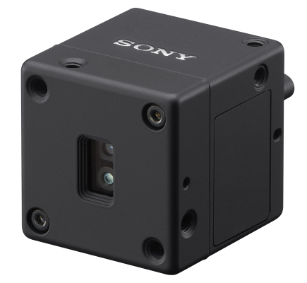
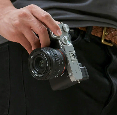
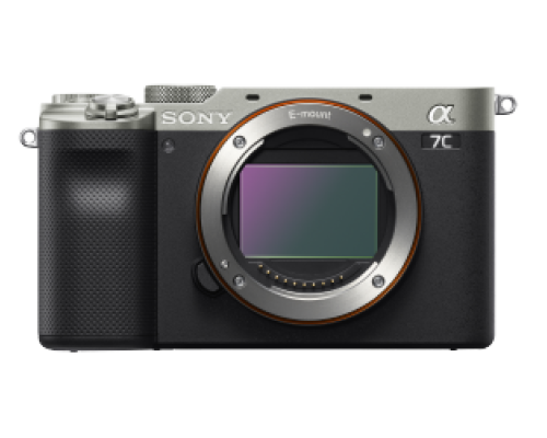
Sony Alpha camera supported by Sony SDK (Software Development Kit)
Sony Alpha camera supported by Sony SDK (Software Development Kit)
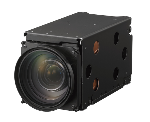
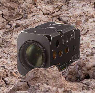
Digital Video Camera using various interfaces (USB, Gigabit Ethernet, Camera link)

Polarised cameras and SDKs
How do on-chip polarisation sensors work? What applications do they enable? And how to get applications created 4 times faster.
Reflective glare can significantly hinder the accuracy and usability of an industrial camera. This is true in controlled visual inspection environments used for the quality-control analysis of components or packaging - where glare can hide a fault, and increase the chance of recalls.
And it is especially true in outdoor applications, such as ITS, where glare caused by highly-variable, unpredictable lighting can not only slow down systems such as automated motorway tolling barriers - for example by not capturing a license plate - it can prevent enforcement cameras from working and therefore reduce the risk of getting caught when, for example, running a red light.
Polarised camera set ups
While the use of polarisation filters has enabled glare to be removed / reduced in image capture and machine vision analysis, each filter could traditionally only act in a single plane. Therefore a system has required either
1) A multi-camera setup: this not only adds complexity and cost when developing and maintaining an application, but using multiple cameras also creates false-positive readings through perspective distortion.
2) A single camera system but with multiple filters being switched at high speed: this eliminates the perspective distortion, but creates a time delay with the changing of each polarisation filter; it also creates a point of system failure through the use of mechanical moving parts.
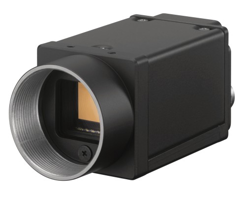
More recently, a third option has become available with the introduction of Sony’s IMX250MZR sensor: the first mass production sensor to incorporate on-chip polarisation; integrating this functionality at the pixel level.
The sensor is already being incorporated into Sony’s XCG-CP510.
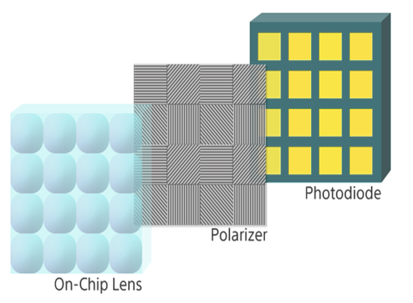
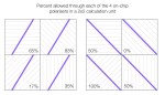
The sensor houses a layer of wire-grid polarizers housed between the microlens and photodiodes. The wire grid is set for each photodiode to filter light in one of four planes - 0o, 90o, 45o, and 135o - with pixels assigned a plane in a 2x2 calculation unit (see fig 1).
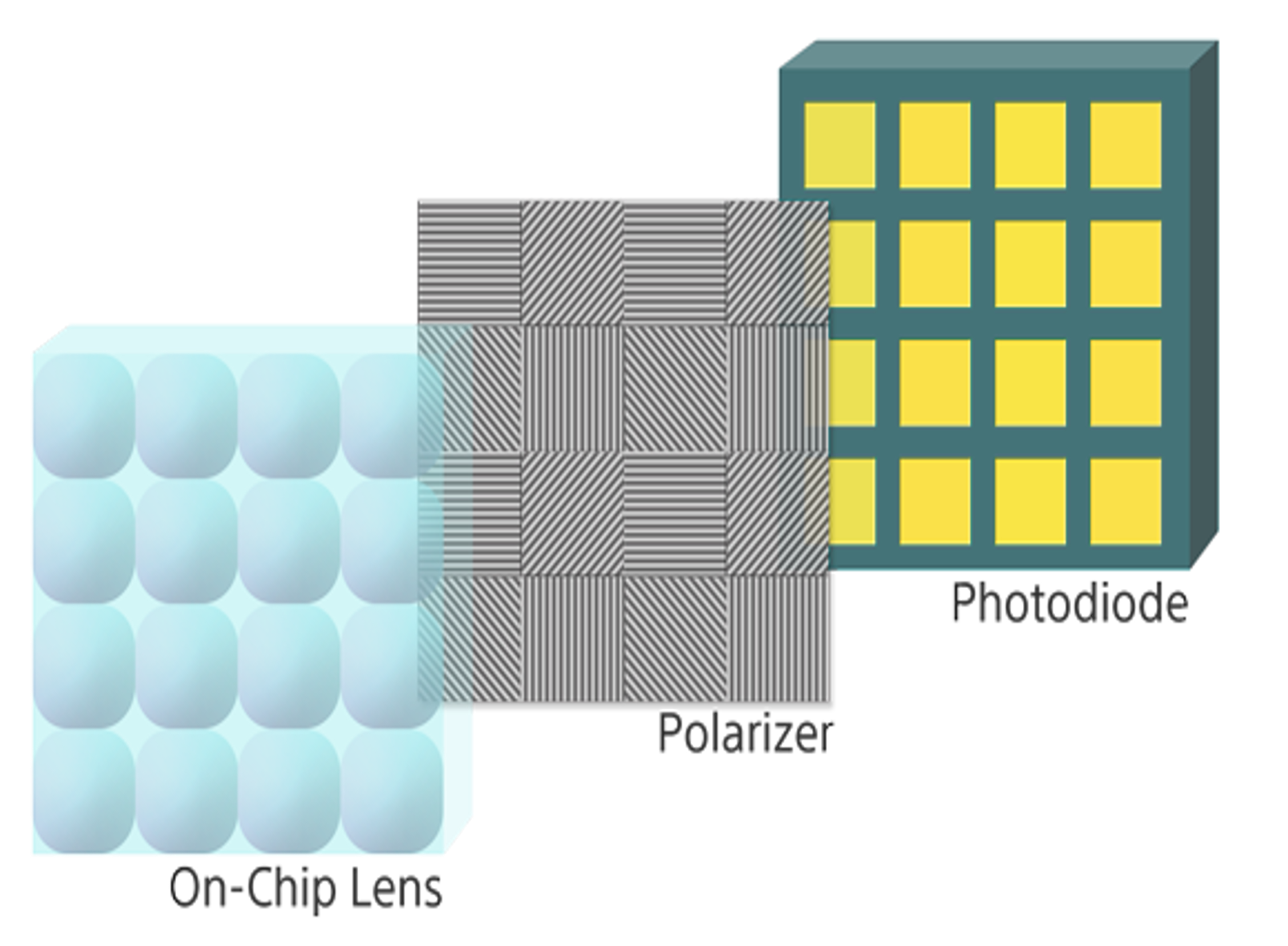
Fig 1 - sensor design and pixel/calculation unit layout
Calculating the precise angle of light
This approach not only creates 4 images, but the data can be used to capture far more information that can be used in industrial and B2B applications.
There is no such thing as perfect polarisation. Some loss will occur even when light is perpendicular to the wire grid (the maximum transmission point). And some unwanted angles of light will come through when light is parallel to the wire grid (the minimum transmission point).
The relationship between the minimum and maximum light enters through the wire-grid polariser is the extinction ratio, with high extinction ratios allowing a more precise detection of the specific angle.
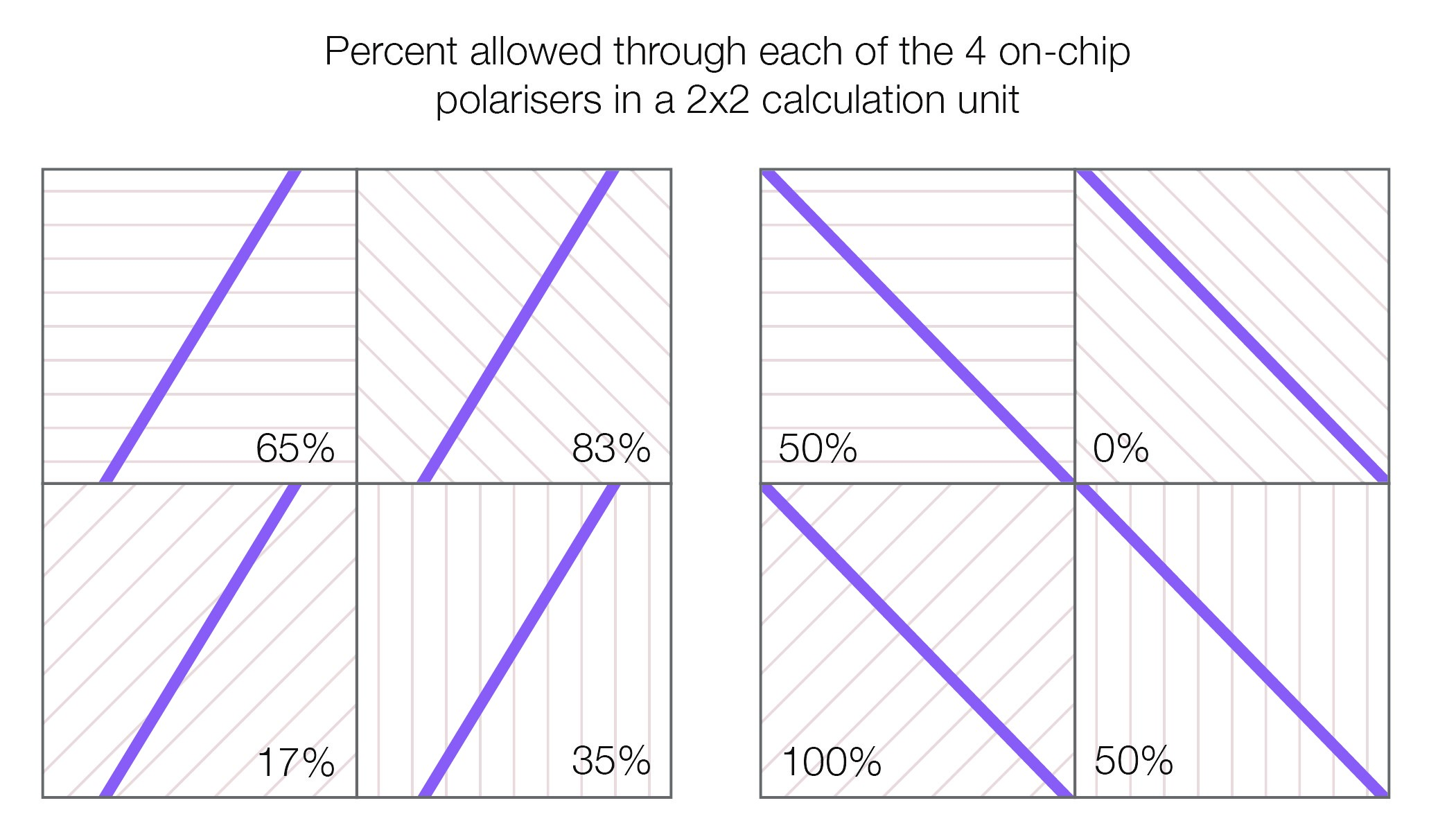
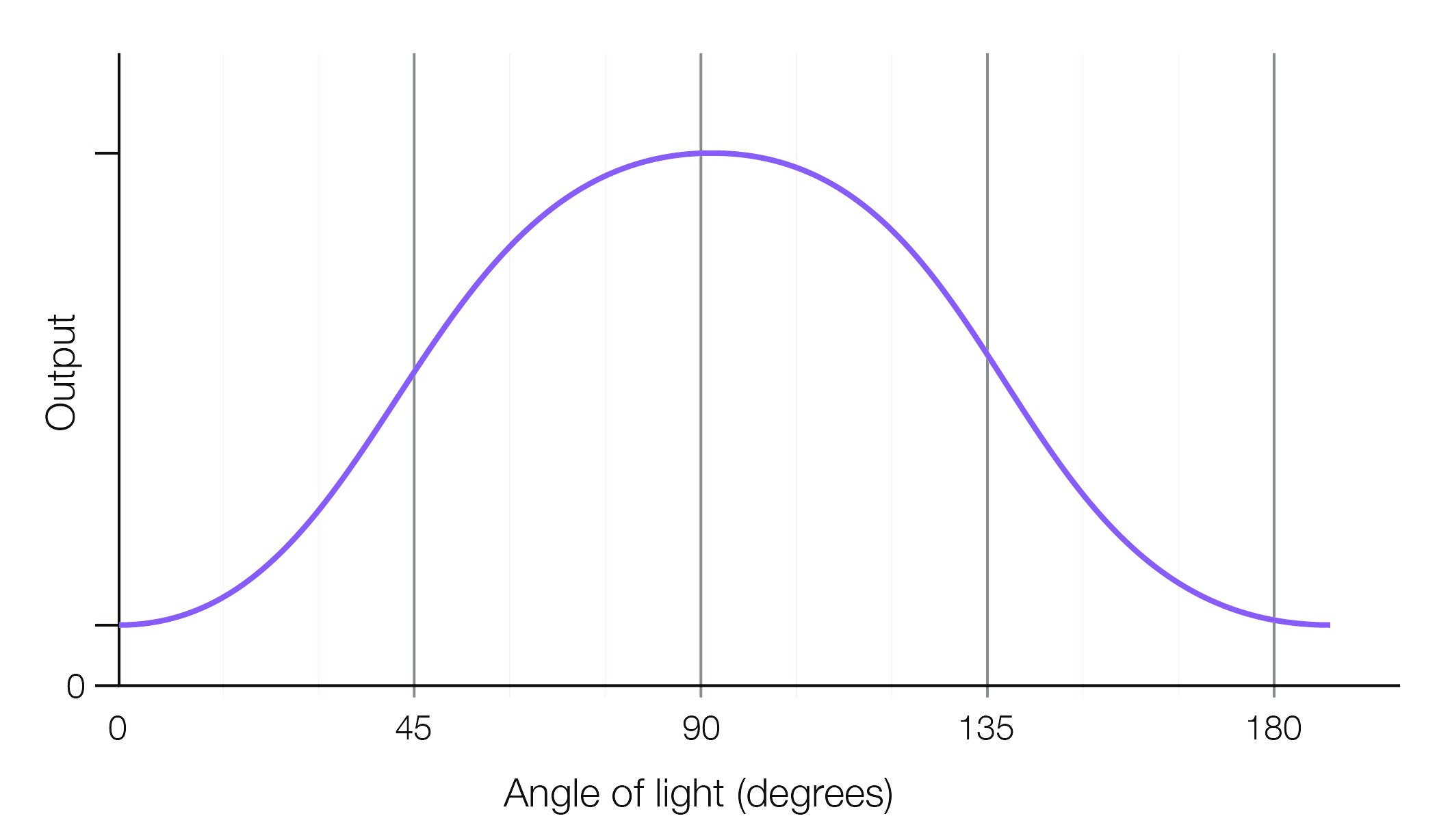
Fig 2 - Transmission still occurs at angles outside of the wire-grid polariser. By using, and comparing the transmission from each photodiode in the calculation unit it’s possible to calculate the precise angle of light
This imperfect nature of a polariser allows you to calculate the precise angle of light coming through, not just for the four specified angles. Comparing the rise and fall in intensities transmitted between each of the 4 pixels in the calculation unit allows you to use Stokes parameters and determine both the precise degree and direction of polarization in any plane.
What the angle of light can tell you
As well as filtering unwanted reflection and glare, application engineers developing vision applications can also use colours for each plane of light to create a graphical representation of how the angle light changes as it goes through / reflects off a surface. This therefore allows the following to be detected:
Weakness detection - stress analysis
The level of stress in a transparent object - such as a piece of perspex / a glass smartphone screen - will transform the angle of light that is refracted slightly. By shining a light through the glass and assigning a colour to the output for each polarisation angle (eg red for 0o, blue for 45o) the altered path of light can be graphically represented to show regions under stress, that would otherwise have gone unnoticed, to be identified and quality control processes improved - see fig 2 and part 4 below.

Fig 3: scratches and stress cause light to reflect differently and this change can be detected via a polarised sensor.
Scratch identification
Like stress, an otherwise hidden scratch or surface defect will also alter the angle of reflection, meaning reflection enhancement can be undertaken to more easily perform surface inspection and scratch detection.
Low-light analysis
In low light situations the outline of objects cannot be easily determined. Polarisation can help improve the contrast of objects by measuring the angle of light reflecting off objects.
This also allows the more accurate identification of hidden and camouflaged items that would normally blend into the background using visual spectrum or thermal imaging cameras - be they man-made or an animal. The technique has proven to be particularly effective in capturing images underwater, where the refractive properties have been shown to vary according to location, depth, time of day and direction. Indeed, several sea creatures rely on evolved polarised light sensors to both perform local/ long-distance navigation and render their prey’s camouflage ineffective.
Glare elimination
The accurate analysis of complex objects (from electronic components and mechanical objects to fruit and vegetables) and reflective materials (from pharmaceutical packaging to a car windscreen) can often be restricted by reflections. Additionally, for outdoor applications - such as drone-based imaging and traffic inspection systems - the variation in light intensity / angle of light, that alters (often unpredictably) throughout the day means glare can significantly affect the quality of captured images.
Remove this glare will improve accuracy - for example the contents of rounded drug blister packs can be observed using a single, static camera; and traffic monitoring cameras can record not just that a dangerous road violation took place (eg speeding / red-light running), but more reliably capture the number plate, as well as the driver and if they’re using a mobile phone.

Fig 4 - elimination of glare from a windscreen reveals a disabled badge to simplify the policing of parking zones
Polarised vision cameras and application development
However, industry surveys suggest there is a significant barrier to adoption: the skillsets (and therefore ability) of system developers to work with the new sensor technology easily. Indeed, development time for a typical application being between 6 and 24 months (depending on the application / team).
To simplify application development, Sony has developed the first, and so far only, SDKs for polarised sensors, the XPL-SDKW (for Windows) and the XPL-SDKLJ for the Nvidia Jetson AI computing platform.
The SDKs help cut development to 6-12 weeks (again based on the application developed and the team).
What’s included in the SDKs
The SDKs include reference library applications and give support functions (including demosaic and raw extraction). Additional features include a ‘Cosine fit’ to allow a developer to define a virtual polariser angle for the image and an ‘Average’ function that enables the creation of a non-polarized image from the raw data for a simultaneous comparison of the polarised and standard-camera images.
And preprocessing functions allow the calculation of various polarisation specific information, such as the ‘Degree of Polarisation’, ‘Stokkes Vector’ and the ‘Surface Normal Vector’.
At the higher-end level, ‘Applications-Oriented’ functions have been implemented to manage reflections and measure stress.
Conclusion
Reflective glare hinders accuracy in both industrial and outdoor B2B applications. Polarised cameras such as the XCG-CP510 can give the clarity needed in such applications.
And SDKs such as the XPL-SDKLJ and XPL-SDKW can cut the development time by a factor of 4.
To find out more please visit Sony’s polarised camera pages or talk to one of our team.